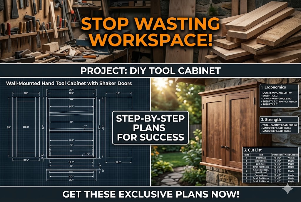
Master Woodworking Storage Strategy: Shaker-Style Wall Solutions
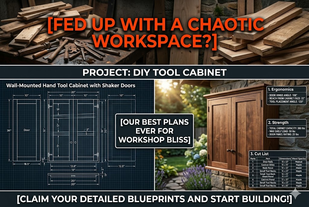
Maximizing small shop square footage requires utilizing vertical space with smart, heavy-duty cabinetry frameworks. Implementing a professional Wall-Mounted Hand Tool Cabinet with Shaker Doors allows craftspeople to secure premium cutting tools and layout gear inside an enclosed, clean environment. Building your storage units from precise, calculated layouts ensures that doors line up flawlessly and components remain completely stable over long periods of heavy daily operational use.
This build guide outlines the exact material standards, machining tolerances, and hardware requirements needed to assemble an industrial-grade hanging tool station. By integrating classic frame-and-panel engineering with modern high-tensile mechanical fasteners, your cabinet carcass will easily resist sagging under substantial tool loads. Review the comprehensive layout specifications below to streamline your shop organization setup and protect your fine tool investments from airborne workshop debris.
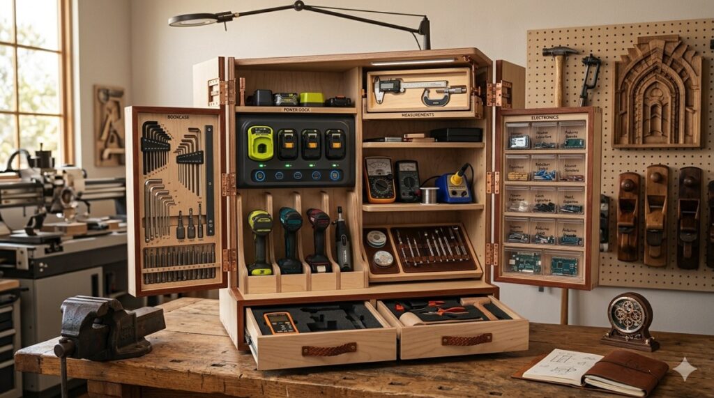
Organizing sensitive woodworking hand tools like premium hand planes, chisels, and layout squares requires a secure, dust-free enclosure that prevents rust and edge damage. Leaving expensive tools exposed on open shelves invites rust-inducing moisture and airborne shop grime, leading to premature edge dulling and a massive waste of money. Utilizing an engineered vertical storage unit optimizes floor space while keeping fine layout equipment protected inside a rigid, flat frame. Woodworkers can Download the professional build blueprints right now to establish full structural security and eliminate tool layout hassle.
Constructing an elite wall storage frame requires sourcing 19mm / 3/4” Douglas Fir plywood panels engineered to pass the Janka hardness test at approximately 660 lbf / 2900 N for optimal structural deflection resistance. The primary framework must be assembled using high-tensile SS 410 stainless steel mechanical fasteners driven via a deep-recess Torx drive to prevent bit slippage and head shear under high load. Builders must deploy digital calipers to check tongue-and-groove alignments, ensuring all joint tolerances remain within a strict 0.5mm / 1/32″ envelope to counteract seasonal wood expansion and contraction. Pre-drilling all hardware holes with an adjustable countersink bit shields the outer ply veneers from grain breakout, keeping the final framework perfectly flat and ready for flush hinges.
QUICK-START EXECUTION GUIDE
- Material Selection: Acquire stable Douglas Fir plywood to guarantee excellent stiffness and high pull-out resistance along the back panel.
- Stock Inspection: Verify sheet material consistency using digital calipers before cutting any primary carcass pieces.
- Carcass Processing: Section the outer box components precisely with a miter saw with digital angle finder to maintain square lines.
- Joinery Cutting: Machine the traditional tongue-and-groove frames for the panel doors, leaving a clean 0.5mm / 1/32″ expansion gap.
- Pilot Hole Preparation: Pre-drill all carcass fastening paths using a sharp countersink bit to safeguard the end grain from splitting.
- Hardware Assembly: Secure the heavy hanging French cleats and structural door hinges using heavy-duty SS 410 Torx screws.
- Blueprint Retrieval: Accelerate your workshop organization setup immediately when you Download the professional build blueprints to access complete cutting lists.
The Material-Matrix (Wood Choice vs. Environment)
| Material Category | Nominal Thickness | Environmental Resilience Factor | Deflection & Sag Risk |
|---|---|---|---|
| Douglas Fir Plywood | 19mm / 3/4” | High resistance to seasonal shop humidity shifts | Exceptionally low (under 0.5mm / 1/32″) |
| Standard MDF Board | 19mm / 3/4” | Low (absorbs moisture rapidly, causing fastener failure) | High risk of sudden structural sagging |
| Baltic Birch Plywood | 18mm / 23/32” | Superb dimensional stability across varying climates | Minimal risk under immense tool weights |
| Melamine Particle Board | 19mm / 3/4” | Poor dampness defense (edges chip and swell easily) | Severe risk of core blowout at stress points |
🛠️ MASTER CRAFTSMAN PRO-TIP: THE COOPERING EXPANSION BUFFER
When assembling the flat center panels for your Wall-Mounted Hand Tool Cabinet with Shaker Doors, never glue the inner solid wood panels into the grooved door frames. Leave the panels completely free-floating inside the tongue-and-groove slots with a 0.5mm / 1/32″ spacing allowance around the outer perimeter. This intentional cushion prevents the outer frame joints from busting open when humidity spikes swell the wood fibers.
➜ Secure the industrial woodworking blueprints to construct your vertical tool storage unit (START)
Heavy-Duty Carcass Engineering and Vertical Load Distribution
Building an industrial-grade hanging tool repository using a Wall-Mounted Hand Tool Cabinet with Shaker Doors configuration requires a firm understanding of structural load distribution. Heavy hand planes, dense cast-iron spokeshaves, and massive framing chisels exert immense continuous downward forces along the back mounting panel. Crafting the main cabinet box out of stable 19mm / 3/4” Douglas Fir plywood ensures a rock-solid foundation that completely eliminates structural flexing or bowing under high weight stress. Woodworkers must keep all sheet good cuts within a strict 0.5mm / 1/32″ margin to guarantee that the outer cabinet walls clamp together perfectly square on the assembly bench. Verifying your layout lines with a miter saw with digital angle finder ensures that every corner joint fits tightly, preventing annoying structural racking issues when the heavy cabinet is loaded to maximum capacity.
Securing the heavy panel components of your Wall-Mounted Hand Tool Cabinet with Shaker Doors framework requires top-tier industrial mechanical fasteners that will not snap under continuous shear weight. Driving high-tensile SS 410 stainless steel screws with a deep-recess Torx drive profile ensures a rigid joint lockup without risking head stripping or driver bit slippage. Pre-drilling all fastener paths with a specialized countersink bit prevents the dense plywood layers from splitting near the outer edges, keeping all screw heads sitting perfectly flush with the wood grain surface. Regularly checking your door opening squareness with high-precision digital calipers guarantees that the front clearance borders operate with an exact safety buffer. Following these precise engineering standards ensures your Wall-Mounted Hand Tool Cabinet with Shaker Doors blueprint yields a sturdy, hassle-free structure that stays locked to your shop wall.
🛠️ MASTER CRAFTSMAN PRO-TIP: THE REAR CLEAT LOCKOUT
When assembling the rear panel for your Wall-Mounted Hand Tool Cabinet with Shaker Doors, always recess your 19mm / 3/4″ French cleat directly into a matching rebate along the top interior edge of the carcass back. This flush-mounting layout transfers the entire downward shear load of your heavy hand tools directly into the solid wood framing rather than relying entirely on the holding power of mechanical screw threads driven through thin backing plies.
➜ Download the exact tool stabilization blueprints to build your heavy-duty wall cabinet now (QUALITY)
Component Cost Metrics and Structural Hardware Budgeting
Successfully executing high-performance Wall-Mounted Hand Tool Cabinet with Shaker Doors plans relies on balancing component material costs against long-term structural value retention. Cutting corners by purchasing cheap hardware or unstable composite boards to save money leads to rapid structural warping and a complete waste of money under the weight of heavy hand planes. Utilizing stable 19mm / 3/4” Douglas Fir plywood ensures a rock-solid protective cabinet base that eliminates the risk of joint separation under heavy loads. Budgeting for premium SS 410 structural Torx fasteners and precise mechanical hardware guarantees that your Wall-Mounted Hand Tool Cabinet with Shaker Doors project yields a rigid wall station that remains completely stable over decades of heavy service.
The Cost-Calculator (Raw Materials vs. Hardware)
| Component Description | Material & Specification | Estimated Cost Metric | Structural Functionality |
|---|---|---|---|
| Cabinet Shell Panels | 19mm / 3/4” Douglas Fir Plywood | $55.00 – $75.00 per sheet | Main heavy load-bearing cabinet carcass |
| Industrial Fasteners | SS 410 Stainless Steel Torx Screws | $12.00 – $18.00 per pack | Rigid joint lockups and intense shear resistance |
| Pre-Drill System | Carbide Countersink Bit with Stop Collar | $14.00 – $20.00 per unit | Clean pilot paths to prevent ply separation |
| Door Frame Stock | Premium Solid Hardwood Planks | $35.00 – $50.00 per board | Flat, stable frames for classic shaker doors |
Maintaining exact dimensional control during the assembly phases of your Wall-Mounted Hand Tool Cabinet with Shaker Doors keeps your components square. Double-checking every panel cutout with high-precision digital calipers keeps your component spacing within a strict 0.5mm / 1/32″ margin, allowing for natural atmospheric fluctuations without binding the front panels. Pre-drilling fastener paths protects the internal wood plies from sudden structural blowout when securing heavy hanging hardware into the base walls. Relying on the professional build blueprints ensures you purchase the exact material quantities required, saving money by eliminating unnecessary cutting errors on premium wood sheet goods.
🛠️ MASTER CRAFTSMAN PRO-TIP: THE STOP COLLAR CALIBRATION
When using a countersink bit to prepare fastener channels for your Wall-Mounted Hand Tool Cabinet with Shaker Doors, always utilize a mechanical stop collar adjusted to the exact head depth of your SS 410 structural Torx screws. This prevents over-drilling into the 19mm / 3/4” plywood core, maintaining maximum fiber density around the threads and guaranteeing supreme pull-out resistance under heavy tool weights.
➜ Secure your material list and cutting schedules by downloading the plans right now (MATERIAL)
Sequential Joinery and Internal Storage Machining Protocols
Executing the joinery for high-capacity Wall-Mounted Hand Tool Cabinet with Shaker Doors plans requires a clean, systematic machining strategy on the shop floor. Cutting deep sliding dados, custom tool grooves, and structural dividers into large 19mm / 3/4” Douglas Fir plywood panels generates massive amounts of fine wood dust that can pack into the joints. Utilizing an industrial shop vacuum system connected directly to your router shroud keeps the workspace clear of debris, allowing you to accurately follow your tool layout lines. Verifying the width of every single groove with digital calipers keeps your joinery within a strict 0.5mm / 1/32″ tolerance envelope. This precise spacing is vital to ensure that your Wall-Mounted Hand Tool Cabinet with Shaker Doors frame fits together without warping the outer structure.
Assembling the inner shelving grid of your Wall-Mounted Hand Tool Cabinet with Shaker Doors demands clean mechanical fastening rather than heavy surface gluing. Standard wood glue locks components completely rigid, which can cause the plywood plies to buckle or split during rapid seasonal humidity shifts. Driving high-tensile SS 410 stainless steel Torx screws through pre-drilled countersunk holes ensures the internal frame stays secure while allowing natural microscopic wood movement. A dedicated impact driver allows you to sink each fastener flush into the cabinet walls without risking bit slippage or structural wood blowout. Following the professional build blueprints ensures that every dado line, screw location, and edge alignment on your Wall-Mounted Hand Tool Cabinet with Shaker Doors matches up perfectly to resist long-term workshop vibrations.
🛠️ MASTER CRAFTSMAN PRO-TIP: THE DADO COMPONENT CLEARANCE
When machining the horizontal dado channels for your Wall-Mounted Hand Tool Cabinet with Shaker Doors, always cut the grooves exactly 0.5mm / 1/32″ wider than the actual thickness of the sliding drawer dividers. This tiny clearance gap acts as an expansion buffer, preventing the internal shelves from swelling, binding, or jamming tightly inside the cabinet framework when summer humidity levels rise.
➜ Access the complete technical cutting schedules to eliminate workshop assembly errors (WORKSHOP)

Time-Stamped Execution Phases and Step-by-Step Milestones
Constructing a durable hanging repository using Wall-Mounted Hand Tool Cabinet with Shaker Doors blueprints relies on following a strict, orderly workflow schedule. Attempting to rush through the cutting phases without verifying your panel dimensions leads to misaligned tracks, structural instability, and a severe waste of material. By structuring your shop time into distinct, manageable phases, you guarantee that every component of your Wall-Mounted Hand Tool Cabinet with Shaker Doors fits together with absolute precision. Utilizing high-grade 19mm / 3/4” Douglas Fir plywood ensures that the structural carcass remains dead flat as you progress through each progressive layer of the assembly process.
The Planning-Table (Time-stamped Execution Phases)
| Phase ID | Workflow Milestone | Duration Metric | Quality Control Check |
|---|---|---|---|
| Phase 1 | Material Allocation & Panel Breakdown | 1.5 – 2 Hours | Verify sheet thickness with digital calipers |
| Phase 2 | Dado Machining & Frame Grooving | 2.0 – 3.5 Hours | Maintain joinery tolerances within 0.5mm / 1/32″ |
| Phase 3 | Pre-Drilling & Shaker Frame Profiling | 1.0 – 1.5 Hours | Use specialized bit to prevent edge ply splitting |
| Phase 4 | Mechanical Fastening & Door Hanging | 2.5 – 4.0 Hours | Secure frame using SS 410 structural Torx screws |
As you shift into the final assembly milestones of your Wall-Mounted Hand Tool Cabinet with Shaker Doors, precision hardware installation becomes your primary focus. Driving high-tensile SS 410 stainless steel Torx screws through the pre-drilled pilot holes ensures that the cabinet frame can withstand continuous workshop vibrations from adjacent machinery without sagging. Double-checking your diagonal measurements ensures the carcass stays perfectly square before you mount any internal sliding tracks, tool holders, or front panels. Following the professional build blueprints provides a clear, reliable path through every stage of the build, guaranteeing an elite Wall-Mounted Hand Tool Cabinet with Shaker Doors setup that stands the test of time.
🛠️ MASTER CRAFTSMAN PRO-TIP: THE DIAGONAL SQUARE CHECK
Before driving any final SS 410 structural Torx screws into the outer carcass of your Wall-Mounted Hand Tool Cabinet with Shaker Doors, always measure the box diagonally from corner to corner in an ‘X’ pattern. If the two layout measurements differ by more than 0.5mm / 1/32″, use a parallel bar clamp on the longer diagonal to pull the frame back into a perfectly square orientation before the mechanical fasteners lock it down permanently.
➜ Download the systematic execution blueprints to streamline your workshop build process (SEQUENCE)
Tool Calibration Preservation and Internal Compartment Layouts
The internal divider configuration of high-performance Wall-Mounted Hand Tool Cabinet with Shaker Doors plans must prioritize absolute structural stability. Standard toolboxes that permit uninsulated metal-on-metal contact will nick delicate instrument parts, causing serious layout errors and permanent alignment damage during workshop transport or daily use. Dividing the inner cavity of your Wall-Mounted Hand Tool Cabinet with Shaker Doors into specialized padded sub-drawers allows woodworkers to store multiple fragile bits, accessories, and blades safely side by side. Utilizing stable 19mm / 3/4” Douglas Fir plywood for these internal tray dividers ensures that heavy engineering components remain perfectly supported without sagging or rubbing against adjacent wooden storage walls.
Securing these heavy internal trays inside your Wall-Mounted Hand Tool Cabinet with Shaker Doors requires robust mechanical joinery that won’t warp or buckle under continuous heavy operational leverage. Driving high-tensile SS 410 stainless steel Torx fasteners into pre-drilled channels ensures that your mechanical hinge components stay rigidly attached to the structural frame of your Wall-Mounted Hand Tool Cabinet with Shaker Doors. Verifying the internal spacing clearance with digital calipers ensures that every sliding component operates with a clean 0.5mm / 1/32″ safety buffer to prevent seasonal friction locks. Relying on the professional build blueprints ensures that your final layout maximizes every square inch of available cabinet space while protecting your expensive hand tooling investments.
🛠️ MASTER CRAFTSMAN PRO-TIP: THE AIR-CUSHION EXPANSION GAP
When constructing precision tool holders for your Wall-Mounted Hand Tool Cabinet with Shaker Doors, always leave an air-cushion expansion gap of 0.5mm / 1/32″ between the custom tool racks and the main inner cabinet carcass. This small relief margin stops the wooden holders from expanding tightly against the outer wall cabinet framing during humid seasons, preventing high-friction sticking and allowing you to access delicate layout gear with a light, effortless pull.
Hardware Selection Criteria and Fastener Tier Comparison
Selecting the correct mounting hardware for your Wall-Mounted Hand Tool Cabinet with Shaker Doors directly impacts how well the finished structure handles daily workshop abuse. Low-grade utility screws will snap or strip when driven into dense 19mm / 3/4” Douglas Fir plywood sheet goods under high-torque conditions. Upgrading your building components to high-tensile SS 410 stainless steel structural Torx screws guarantees excellent shear resistance and long-term protection for your Wall-Mounted Hand Tool Cabinet with Shaker Doors. Verifying your hardware clearances using high-precision digital calipers keeps your tolerances locked within a tight 0.5mm / 1/32″ envelope, ensuring that the heavy doors of your Wall-Mounted Hand Tool Cabinet with Shaker Doors open smoothly without sagging or jamming over time.
The Keuze-Hulp (Beginner vs. Pro Hardware Options)
| Hardware Category | Standard Utility Tier (Entry) | Industrial Engineering Tier (Pro) | Performance Impact Metric |
|---|---|---|---|
| Fastener Drive Type | Traditional Phillips / Pozi Head | Precision Deep-Recess Torx Drive | Eliminates cam-out and head stripping |
| Material Composition | Zinc-Plated Carbon Steel | SS 410 Grade Stainless Steel | Complete corrosion and rust immunity |
| Pre-Drilling Method | Standard Twist Drill Bit | Countersink Bit with Adjustable Stop | Prevents surface splitting and ply tear-out |
| Hinge Configuration | Standard Light-Duty Butt Hinges | Heavy-Duty Interlocking Hinge Straps | Instant stability under heavy vertical load |
Investing in pro-tier hardware components for your Wall-Mounted Hand Tool Cabinet with Shaker Doors eliminates structural warping issues caused by heavy tool weights and changing workshop conditions. Sinking every mechanical screw through a cleanly pre-drilled pilot path allows the wood plies of your Wall-Mounted Hand Tool Cabinet with Shaker Doors to clamp together tightly without structural deformation. Using specialized carbide bits ensures the screw heads sit perfectly flush with the wood surface, keeping internal tool doors operating with maximum clearance. Adhering to the professional build blueprints removes all guesswork from your hardware shopping lists, allowing you to build an elite, industrial-grade Wall-Mounted Hand Tool Cabinet with Shaker Doors on your very first try.
🛠️ MASTER CRAFTSMAN PRO-TIP: THE THREAD LUBRICATION TRICK
When driving heavy SS 410 structural Torx screws into dense Douglas Fir plywood frames for your Wall-Mounted Hand Tool Cabinet with Shaker Doors, rub the threads of each fastener against a block of solid beeswax or paraffin wax before assembly. This non-reactive wax coating significantly reduces insertion friction, preventing the screw from binding up or snapping halfway into the wood grain while maintaining full mechanical holding power.
➜ Secure the exact industrial-grade hardware schedules and material cut lists right now (START)
Start Building Immediately
Constructing a durable hanging repository using Wall-Mounted Hand Tool Cabinet with Shaker Doors plans is the ultimate way to eliminate workshop tool clutter and safeguard expensive precision edge investments. Utilizing premium 19mm / 3/4” Douglas Fir plywood ensures a rock-solid, stable carcass that resists structural warping from ambient shop humidity shifts. By maintaining a strict building tolerance within a 0.5mm / 1/32″ margin across your Wall-Mounted Hand Tool Cabinet with Shaker Doors frame and securing your primary joints with high-tensile SS 410 stainless steel Torx screws, you eliminate the risk of structural racking over time. Pre-drilling clean fastener paths with an adjustable countersink bit ensures that every hardware component on your Wall-Mounted Hand Tool Cabinet with Shaker Doors fits together perfectly flush, preventing edge splitting and guaranteeing industrial-grade durability.
The time for planning is complete; it is now time to transform your shop floor organization. Do not compromise your precision hand planes and chisels by leaving them mounted on unstable, flexing surfaces that offer no protection against rust. By investing your time into executing this Wall-Mounted Hand Tool Cabinet with Shaker Doors build guide, you establish a professional, long-lasting storage ecosystem that keeps your essential shop tools clean, accurate, and immediately accessible. Grab your digital calipers, calibrate your shop machinery, and use the professional build blueprints to build a high-performance Wall-Mounted Hand Tool Cabinet with Shaker Doors upgrade that will serve you flawlessly for decades to come.
🛠️ MASTER CRAFTSMAN PRO-TIP: THE RADIAL CUT INSPECTION
Before you finalize the assembly of your Wall-Mounted Hand Tool Cabinet with Shaker Doors, run a test piece of scrap wood through your workshop machinery to verify your rail and stile alignment lines. Checking your layouts ahead of time ensures that your Wall-Mounted Hand Tool Cabinet with Shaker Doors panel tracks remain perfectly flat and square, keeping your custom measurement doors operating smoothly under maximum load weights without dragging or sticking.
Frequently Asked Questions
What is the best material choice for executing Wall-Mounted Hand Tool Cabinet with Shaker Doors plans?
The most reliable material choice for building a setup from Wall-Mounted Hand Tool Cabinet with Shaker Doors blueprints is 19mm / 3/4” Douglas Fir plywood or premium Baltic Birch sheet goods. These stable materials offer excellent resistance to seasonal atmospheric variations and provide a high Janka hardness rating to prevent structural distortion under the weight of heavy storage equipment. Avoid using cheap particle board or standard MDF cores for your Wall-Mounted Hand Tool Cabinet with Shaker Doors, as they expand rapidly when exposed to humid workshop environments and have poor fastener retention properties.
What internal tolerances must be maintained for heavy machine trays?
When machining the internal slots, door panels, and drawer tracks according to your Wall-Mounted Hand Tool Cabinet with Shaker Doors plans, you must maintain a strict building tolerance within a 0.5mm / 1/32″ margin. Checking your cuts with digital calipers ensures that you leave a tiny expansion buffer. This small gap prevents wood-on-wood binding during high-humidity summer months while keeping the frames of your Wall-Mounted Hand Tool Cabinet with Shaker Doors aligned flat without racking or jamming during daily operation.
Why are high-tensile SS 410 structural Torx screws recommended for this build?
High-tensile SS 410 stainless steel structural Torx screws offer superior shear strength and absolute corrosion immunity in unconditioned shop spaces. Using a deep-recess Torx drive profile prevents screw head cam-out and stripping when driving fasteners into dense plywood frame joints under high-torque conditions during the assembly of your Wall-Mounted Hand Tool Cabinet with Shaker Doors. Pre-drilling all screw channels with a dedicated countersink bit ensures the screw heads sit perfectly flush, keeping the door pathways of your Wall-Mounted Hand Tool Cabinet with Shaker Doors completely free of mechanical obstructions.
Expand Your Workshop Layout
Optimizing a high-performance workspace relies on a fully integrated storage ecosystem where every piece of precision machinery and hand tool has a dedicated, secure home. Building a durable casing using our latest wall cabinet plans is an essential milestone, but its utility is maximized when seamlessly connected to a broader shop organization strategy. Explore our comprehensive collection of blueprint packages, tactical layout guides, and structural upgrades to streamline your workflow and expand your capabilities:
- Main Blueprint Hub: Access a wide variety of premium engineering schematics, industrial tool storage ideas, and professional project layouts directly on our Homepage.
- Workshop Equipment Catalog: Browse our complete collection of heavy-duty shop carts, machine stands, and integrated organization frameworks in the Workshop Solutions & Equipment Category.
- Ultimate Layout Manual: Master the core principles of space utilization, structural storage engineering, and workflow efficiency by visiting our comprehensive Workshop Organization Plans Guide.
- Central Storage Hub: Discover comprehensive layout schematics, hardware lists, and cabinet options across our master Tool Storage Plans resource page.
- Modular Wall Storage: Build an ultra-flexible, high-capacity hanging system for your hand tools using our comprehensive French Cleat Plans.
- Lumber Safety Racks: Prevent expensive boards from bowing or warping over time by constructing our Vertical Lumber Storage Plans.
- Dual-Purpose Machinery Stands: Maximize narrow shop footprints utilizing our rotating, space-saving Flip Top Tool Stand Plans.
- Plywood Handling Carts: Transport and breakdown large, heavy panels safely by implementing our Sheet Goods Cart Blueprints.
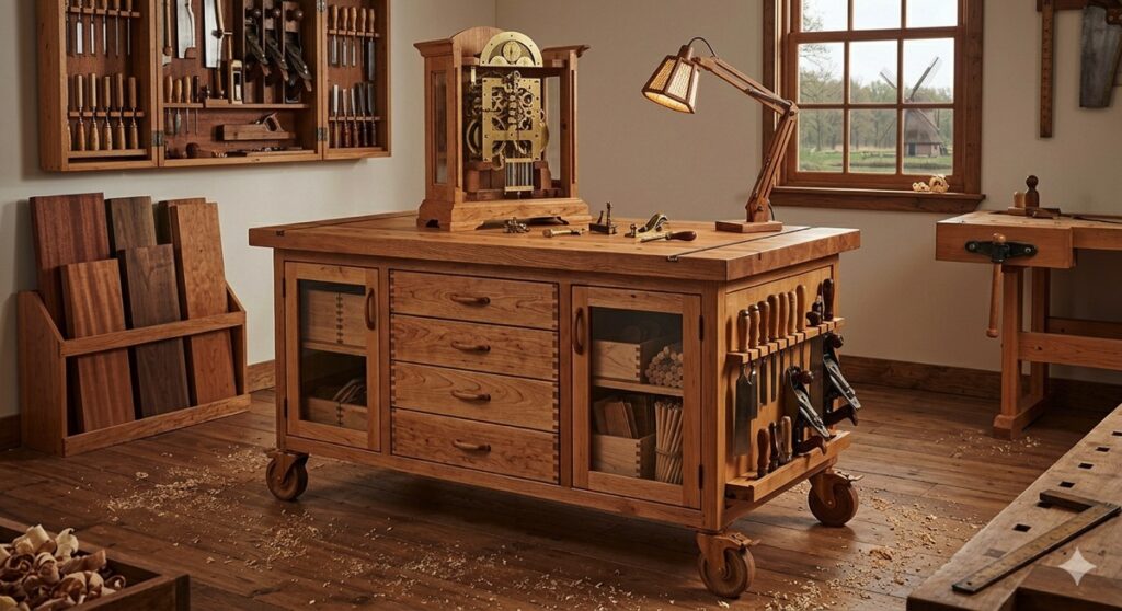
- Heavy Hardware Cabinetry: Organize heavy fasteners, hardware bins, and precision gauges utilizing our Workshop Drawer Cabinet Plans.
- Cordless Power Tool Hubs: Create a dedicated, accessible charging station for your primary drivers using our Power Tool Cabinet Blueprints.
- Mobile Cutting Stations: Build a heavy-duty station with integrated extension supports by adopting our Rolling Miter Saw Station Plans.
- Shop Administration Hubs: Establish a clean, dust-free mobile workspace for planning and digital design via our DIY Mobile Shop Office Plans.
- Compact Machine Risers: Elevate benchtop tooling to comfortable operational heights with our Benchtop Tool Storage Pedestal Plans.
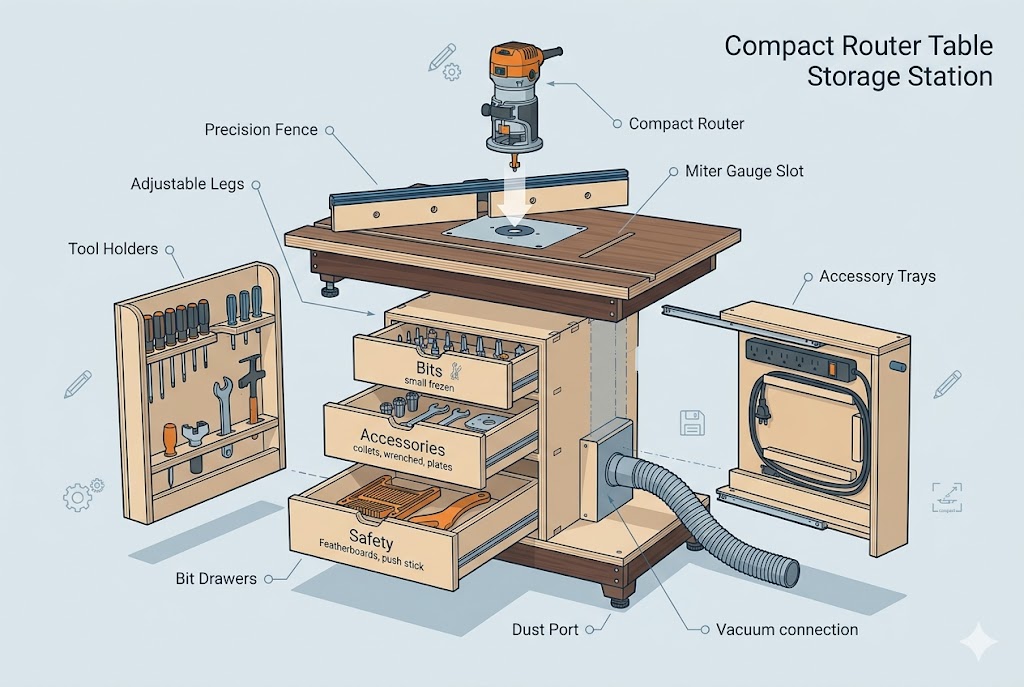
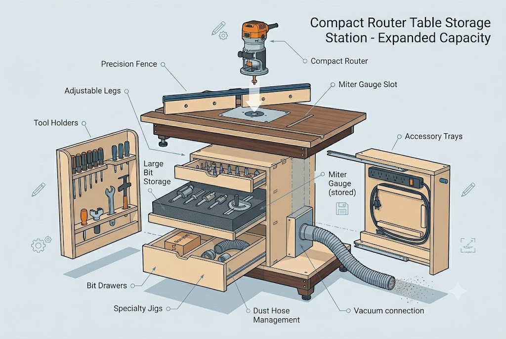
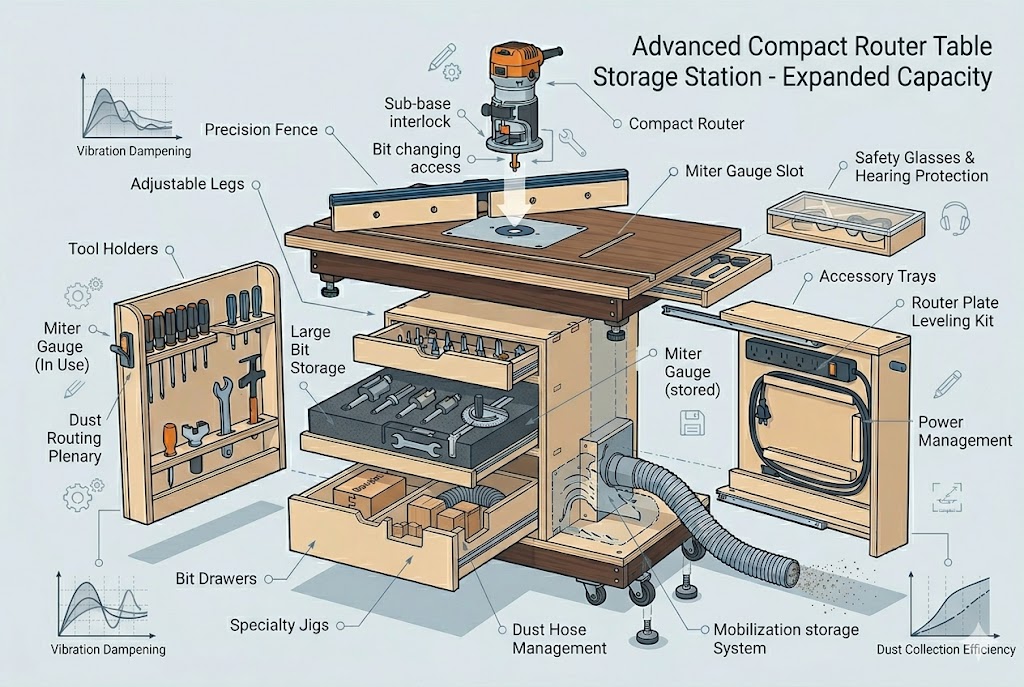
- Integrated Router Enclosures: Combine precision bit tracking and accessory management using our Router Table Storage Station Plans.
- Affordable Storage Panels: Maximize vertical surface areas without breaking the bank by following our Tool Wall on a Budget Guide.
- Heavy Utility Lockers: Fabricate clean, durable wooden casings to shield tools from airborne dust with our Plywood Tool Cabinet Blueprints.
- Battery Power Management: Organize power banks, chargers, and pneumatic lines using our dedicated Charging Station Plans.
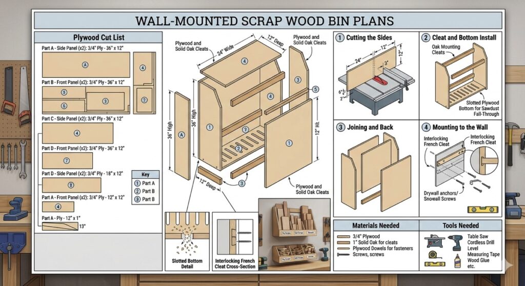
- Off-Cut Sorting Bins: Keep valuable scrap hardwood graded, clean, and immediately accessible with our Wall Mounted Scrap Wood Bin Plans.
- Clamping Fixture Organizers: Prevent heavy clamping bars from slipping or warping by using our stable Clamp Rack Plans.
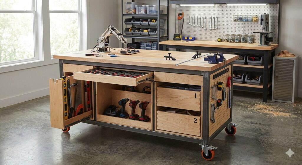
- Heavy Duty Project Tables: Build a flat, rock-solid surface featuring integrated storage trays with our Rolling Assembly Table Blueprints.
- Profiling Accessory Drawers: Safeguard delicate profiling cutters, collets, and wrenches using our Router Storage Station Plans.
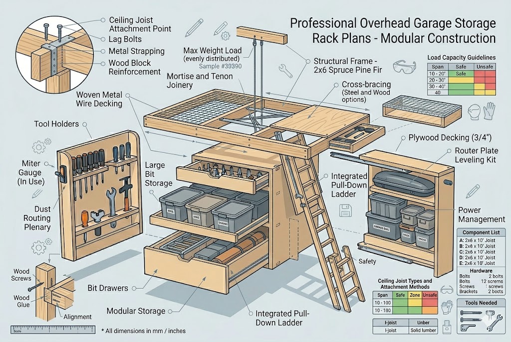
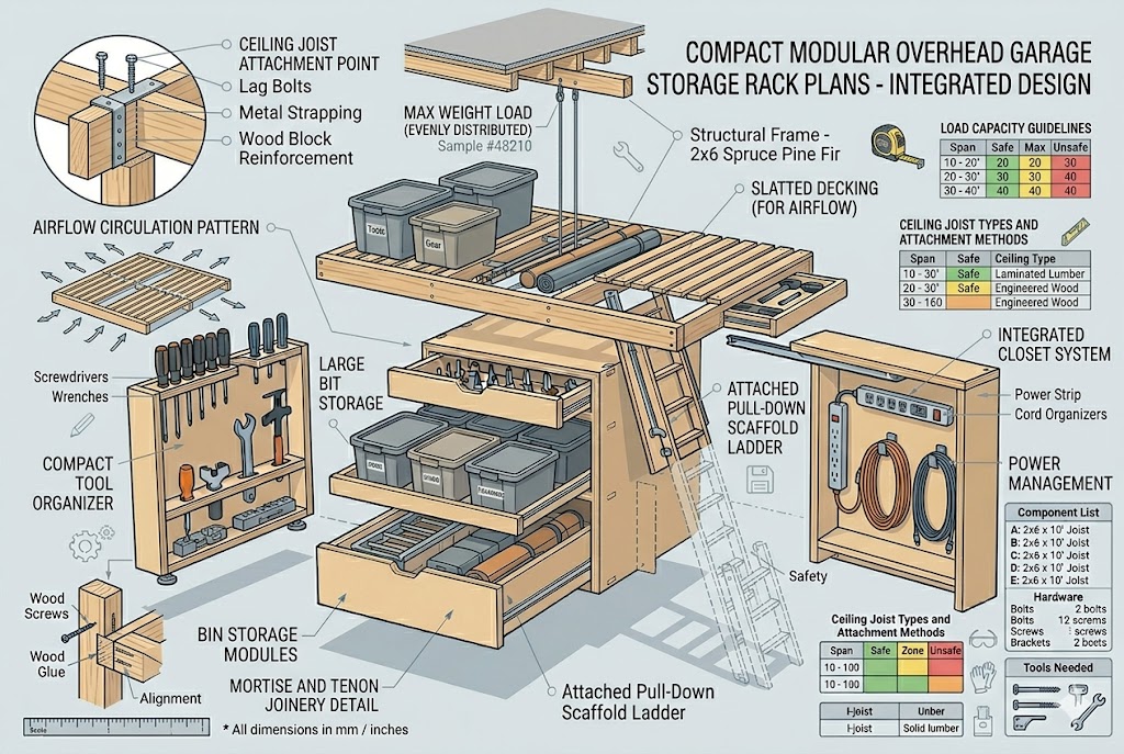
- Ceiling Clearance Frames: Capitalize on unused upper joist space for seasonal storage using our Overhead Garage Plans.
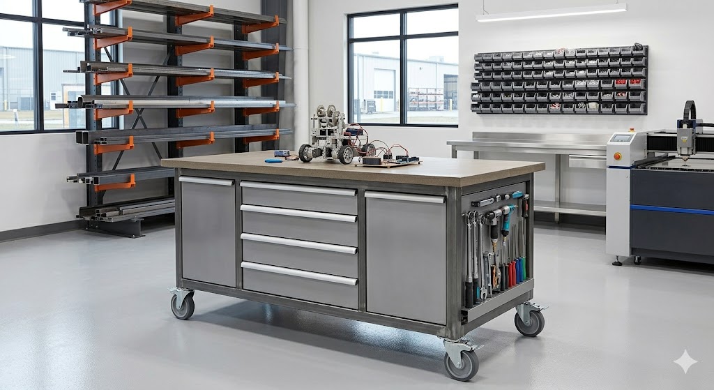
- Industrial Framing Units: Support massive structural loads along open walls using our resilient Heavy Duty Wall Shelving Units Guide.
- Machinery Blade Storage: Isolate sharp table saw plates and routing fences safely from your precision tooling by building our custom Blade & Accessory Cabinet Blueprints.